Defining the Simulation Environment
We start in the redBlocks Simulator by defining the hardware interfaces we plan to use in our example project, by selecting the menu item "Project -> Configure Interfaces". There you configure
- a communication channel with ID 0 that represents a serial interface on a real target
- two digital outputs with ID 0 (e. g. called Led) and 1 (e. g. called AwakeLed) for the LEDs
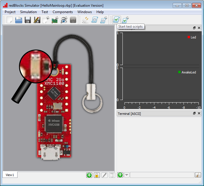
After that, we can add a background image and create view components, i. e. an LED icon for the digital output and a Digital Oscilloscope. The Digital Oscilloscope is accessible via the menu "Windows" (refer to the Documentation via menu "Help" for further configuration information on the various view components and windows). If you like, you can use the following images, so the interface looks like an XMC2Go eval board.