

Setup the Target Project
When compiling a redBlocks application for a target, the same sources are used as for the simulation project. Therefore, we recommend the following directory structure:
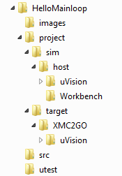
- The common source files are located in the directory src.
- The source files that are needed for simulation are located in the directory project/sim. The subdirectory host contains all source files that are relevant for simulation on the host (a simulation environment for target boards can be set up in directories parallel to the subdirectory host).
- The files for target deployment are located in the directory project/target. In order to be able to support multiple targets in parallel, a subdirectory is created for each target (e. g. XMC2Go). Beneath the target directory, a subdirectory for the cross-development toolchain is created, e. g. uVision, where the toolchain's project and build files are stored.
This directory structure is flexible enought to support multiple different simulation targets and multiple different real hardware targets without the need to reproduce any code.
In order to setup this directory structure along with the basic initialization code for the XMC2Go target, download the XMC2Go template project for uVision and unpack it in the directory project:
In directory XMC2Go you find the files main.cpp (with the target initialization code and application setup) and LowLevelPlatform.h (where the abstract target platform is defined). Directory uVision contains the uVision project files.
Open the uVision project file XMC2Go.uvprojx in directory uVision with the uVision IDE and compile the project. The compile process should finish without any errors.
In order to be able to download and debug the program in the uVision IDE, you need to adjust the J-Link settings:
- Select menu item Project -> Options for Target 'XMC2Go', change to the tab Debug and hit the button Settings.
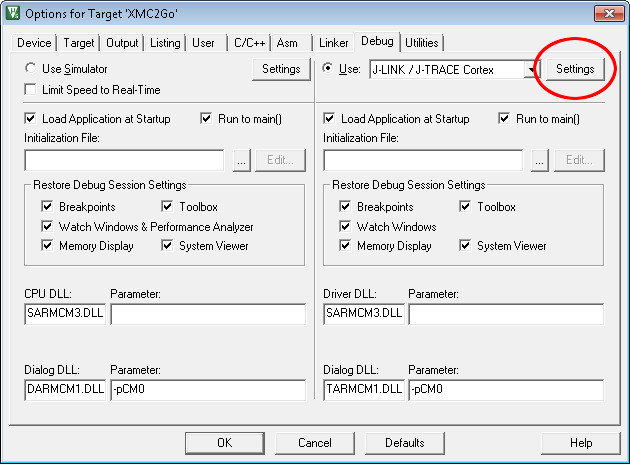
- After that, choose SW in field Port (note that the XMC2Go target must be connected to your computer in order to be able to change this value)
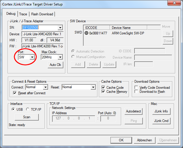
If these settings are not adjusted correctly, you will experience the error "No JLink Device found" when trying to download or debug the application on the target.
When this is done, you may run the application on the target board by starting a debugging session. You will see that one LED is flashing, while the other LED (AwakeLed) is dimmed to medium intensity. This is, because it is permanently switched on and off as the controller leaves sleep mode on each system tick and re-enters it again (see previous tutorial). When being connected to the target with a text terminal program, you can see the target's log output and you can control the flashing LED with the commands '1', '0' and 'f'.
Note that the AwakeLED stays off, when the LED is not flashing and only lights up for a short moment, when a new command is received, just like we were able to observe in the simulator in the previous tutorial.
In order to learn about the structure of the target project and where you need to modify the code in order to conduct own experiments, move on to the next tutorial step.